Integrated Optical Electric Field Sensors: Humidity Stability Mechanisms and Packaging Scheme
Abstract
Integrated optical electric field sensors (IOES) play a crucial role in electric field measurement. This paper introduces the principles of the IOES and quantitatively evaluates the impact of humidity on measurement accuracy. Sensors with different levels of hydrophobicity coatings and hygroscopicity shells are fabricated and tested across the relative humidity (RH) range of 25% to 95%. Results reveal that humidity stability is primarily influenced by water vapor absorption through the sensor shell, which increases its conductivity. This further results in amplitude deviation and phase shift of the sensor output. To address this, an optimal humidity-stable packaging scheme is proposed, which involves using PEEK shell with room temperature vulcanized fluorinated silicone rubber coating. Compared with uncoated ceramic shell, the phase shift of the IOES reduces from 90 to 1 under a RH of 90%. The amplitude deviation of electric field measurement decreases from 20% to nearly zero after a 20-hour humidity experiment conducted under RH of 90% at 30 C. The proposed packaging scheme could be used to improve the humidity stability of the sensors deployed in outdoor environments, especially on ships and coastal areas.
Index Terms:
Electric field measurements, electro-optic sensor, hydrophobic coating, humidity stability, sensor packaging.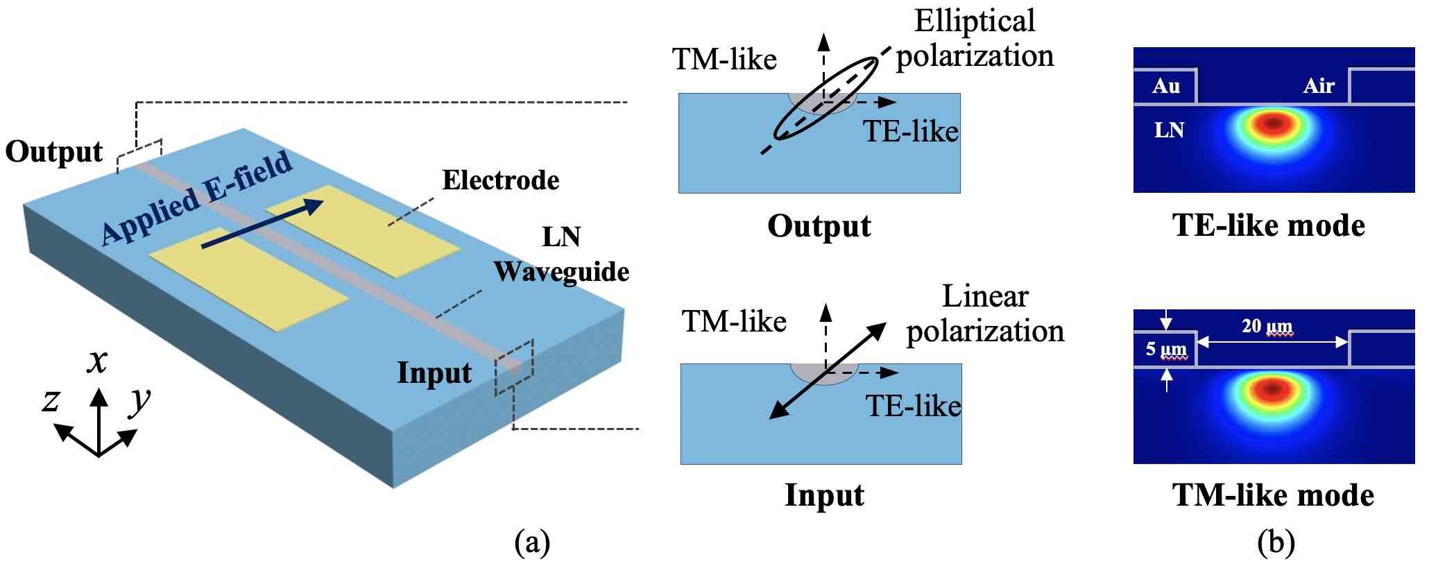
I Introduction
With the flourishing development of the electric power industry, integrated optical electric field sensors (IOES) have gained widespread usage in electric field measurements[1]. These sensors offer several advantages, including wide frequency range, compact size, and non-contact measurement capabilities. They have been applied in various scenarios, such as insulator testing [2], transient overvoltage in substations [3], very fast overvoltage in GIS [4], electromagnetic field around power line [5], AC and DC electric field [6] and intense electromagnetic pulse measurement [7], [8], [9].
However, the environmental stability of IOES based on electro-optic crystals, with lithium niobate (LN) being the most widely used [10], has always been a concern [11],[12]. When the sensors are deployed in outdoor environments, fluctuations in the temperature and humidity can negatively impact the measurement accuracy by affecting the bias point of the sensor. A large number of researchers have conducted studies on the temperature stability of the sensors due to the physical effects exhibited by electro-optic crystals, such as pyroelectric effect and thermo-optic effect [13], [14].
The humidity stability of the IOES refers to its ability to maintain unaltered output under varying humidity levels, including amplitude and phase angle. In 1986, Preston, et al. found that high humidity levels could affect the device reliability, leading them to propose the hermetic fiber-tailed package for LN electro-optic devices [15]. Subsequent studies primarily focused on improving sensor humidity stability through design of the hermetic packaging structure [16],[17]. Until 2009, Li found that even with hermetical packaging, the response characteristics of LN IOES could still be affected by the relative humidity (RH) in the environment [18]. In 2013, Li, et al. further demonstrated through experiments that the stability of IOES is affected by humidity. He proposed that the continuous thickening of water film on sensor shell surface with increasing humidity is the underlying reason that affects humidity stability [19].
The researcher thinks that the humidity stability of the sensor depends on the hydrophobicity of its shell. Through the application of a hydrophobic (HP) coating, achieved by treating the shell surface with epoxide-resin glue, the contact angle (CA) of the shell surface increased from 40 to 85. Consequently, water molecules on the shell surface cannot form continuous water film. This modification enables the sensor to withstand higher levels of RH, reaching up to 85% at 20 C and 50% at 30 C [19]. However, the humidity range still limits the application of IOES, necessitating further research into the humidity stability.
It is also proposed that while a HP film can prevent the penetration of liquid water, it has never been effective for the water vapor transmission through HP materials [20]. HP coatings, including those like room temperature vulcanized silicone rubber (RTV-SIR) [21], may contain small pores that can absorb moisture from the surrounding air [20],[22]. Consequently, this absorbed moisture can condense into liquid water and dissolve into the shell material [23]. The extent of water absorption increases in correlation with both RH levels and the porosity of the coating [24],[25], thereby impacting the electrical properties of the sensor, such as dielectric constant and conductivity [26].
In our experiments, it is observed that the phase shift of the IOES increases to 90 under the RH of 90%, resulting in the invalidation of IOES. With HP coatings, the phase shifts decrease to about 30, which still degrades the measurement accuracy of IOES. Our theoretical models, focused on water vapor thickness and sensor shell conductivity, reveal that the key factor impacting humidity stability is the sensor shell’s hygroscopicity, which causes water vapor absorption and increased conductivity. It contrasts with prior belief attributing humidity stability to sensor shell hydrophobicity. We propose an optimal packaging scheme with a combination of low hygroscopicity in the shell material and low moisture permeability in the HP coating, which improves the phase shift of the IOES to 1 under the RH of 90%. The amplitude deviation of the electric field measurement decreases from 20% to nearly zero after 20 hours testing.
The paper is organized as follows. Section II introduces the principles of the IOES and explores the influence of humidity on the sensor accuracy. Three sensors with different HP coatings are fabricated, and the humidity stability is evaluated. Section III studies the influence mechanisms of the sensor humidity stability by theory and modeling. In Section IV, an optimal packaging scheme is proposed and validated through a long-term testing in a high humidity environment. The proposed packaging scheme to improve the humidity stability could be extended to other sensors as well.
II Principles and Measurement Results
II-A Principle of IOES
The principle of the IOES is based on the Pockels effect of LN, which means the refractive index of electro-optic crystal changes linearly with the applied electric field. The schematic diagram of the IOES is shown in Fig. 1(a). The sensor is based on x-cut bulk LN, and light propagates along z-axis. The principle of the IOES is based on common-path interferometer [1]. The input light is linear polarized by a fiber polarizer, which could be divided into the transverse electric (TE)-like mode and transverse magnetic (TM)-like mode. The former is polarized in y direction, while the latter is polarized in x direction. The optical mode profiles are shown in Fig. 1(b). The waveguide is fabricated by Ti-diffusion with a 7-mm-width titanium stripe. Because of the phase difference of the two modes after propagating through the same waveguide path, the output light is elliptical polarized. A fiber analyzer is used at the output, and then a photodetector converts the optical power into voltage.
The transfer function of the IOES between the applied electric field and the sensor output is
| (1) |
where is the photoelectric conversion coefficient, and is the extinction ratio. is the bias point without applied electric field. and are the effective refractive indexes of the TE and TM-like modes. is the optical wavelength, and is the length of the electrode. is the phase change induced by the applied electric field , where is the component of the electro-optical coefficient of LN, and is the ordinary index of LN [13].
By designing the width and length of the waveguide path, the bias point could be set as /2. Then Eq. (1) is converted into
| (2) |
The output voltage is proportional to the applied electric field .
II-B Experimental setup and influence of humidity
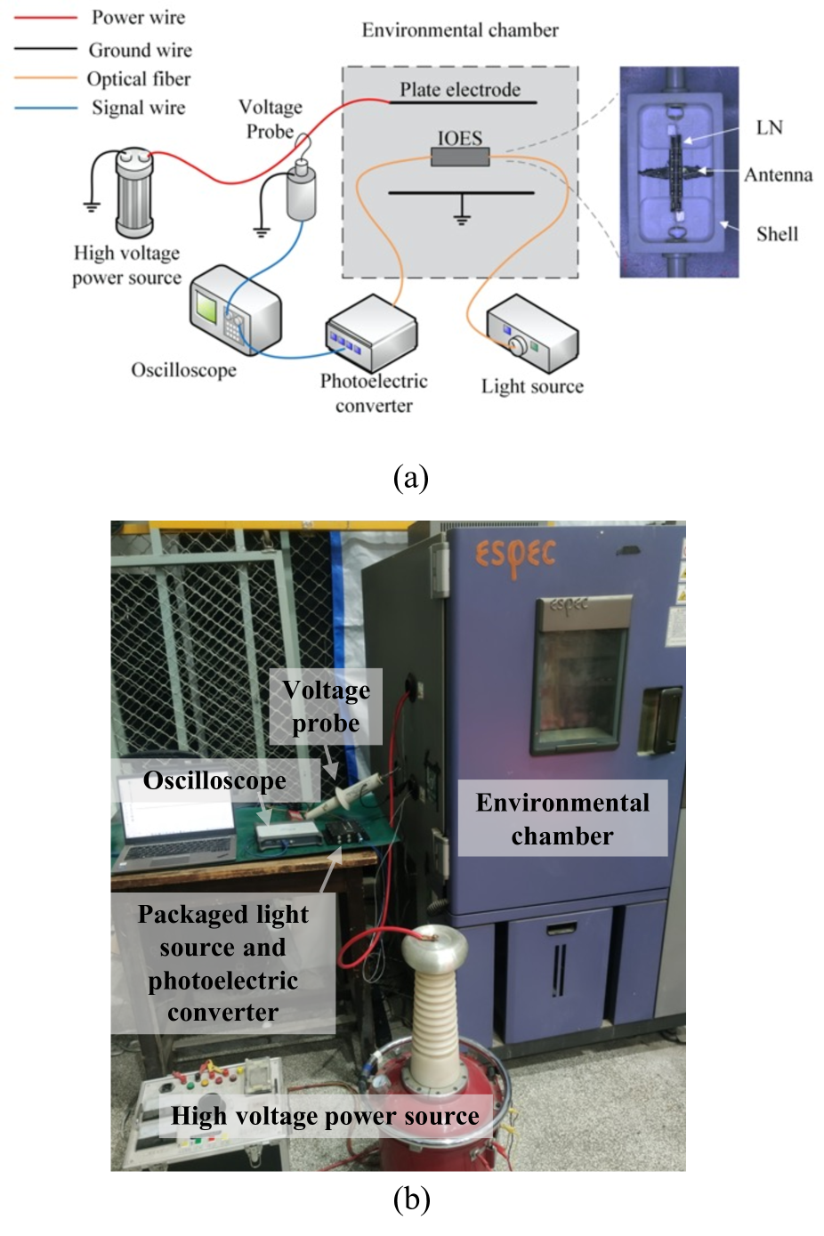
The experimental setup for humidity stability is shown in a schematic diagram and a photograph in Fig. 2(a) and (b), respectively. The inset photograph in Fig. 2(a) shows the sensor inside, which inludes LN crystal, metal antenna and sensor shell (before coated). The environmental chamber (Espec, model EL-02KA) has a temperature (T) range from -40 to 150 C with a control accuracy of 0.5 C and a RH range from 10% to 100%. A 50 Hz power-frequency high-voltage source is connected to a plate electrode, which is settled in the environmental chamber A high-voltage probe is used to measure the applied voltage. The IOES is placed between the plate electrodes, and connected to the outside light source and photoelectric converter through polarization maintaining fibers. The light source and photoelectric converter are packaged together and custom-made by Discoveryoptica Inc. The output power of light source is 250 W and the total insertion loss of IOES is about 3 dB. The utilized optical wavelength is 1310 nm due to its compatibility with low-loss fibers and easy accessibility as a light source. The applied voltage and output of the IOES are simultaneously measured by the oscilloscope.
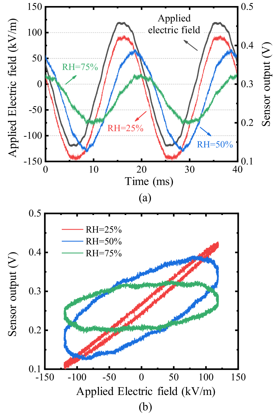
Measured sensor outputs under different humidity levels are shown in Fig. 3. With the increment of RH levels at a rate of 5%/h, the phase shift becomes larger and the output voltage degrades obviously. When the RH reaches 75%, the output voltage decreases to half of the applied electric field. Fig. 3 (b) shows the input-output characteristics corresponding to Fig. 3 (a), also known as Lissajous curve. This shows the phase shift between applied electric field and sensor output more obviously. Therefore, the humidity strongly influences the accuracy of IOES.
In order to quantitatively evaluate the influence of humidity, the figure of merit should be settled first. The amplitude deviation is defined as:
| (3) |
where is the amplitude of measured electric field. is obtained by the high-voltage probe and is derived by the output of the IOES refers to (1) and (2). As the output signal of IOES is voltage, the measured electric field derived by the IOES after drying is used for calibrating measured electric fields.
The phase shift is defined as:
| (4) |
where and are the phase angles of applied and measured electric field.
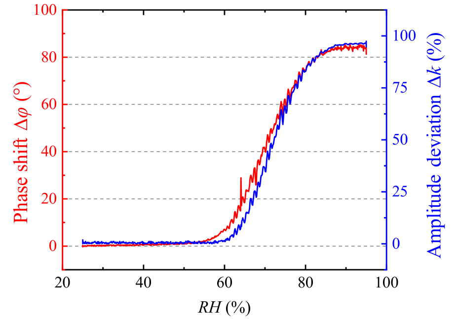
Measured variations in amplitude deviation and phase shift of an IOES at a temperature of 30 C is shown in Fig. 4. These two parameters first keep constant in a low RH level, then increase exponentially as RH increases, and finally saturate to nearly 100% and 90, respectively. It is shown that the amplitude deviation and phase shift change in the same trend. Since the amplitude deviation changes with different applied electric field , which could make varies in different cases (e.g., applied voltage, metal plate gap), phase shift is selected as the figure of merit to characterize the humidity stability of the sensor in the rest of the paper. Smaller phase shift suggests better humidity stability.
II-C Influence of shell hydrophobicity
The influence of shell hydrophobicity on the humidity stability is explored with different HP coatings, providing insights for the design of the humidity-stable packaging schemes. The coatings are applied to the outer surface of sensor shell shown in the inset photograph of Fig. 2(a).
The sensor coating is required to exhibit three properties: good hydrophobicity, strong adhesion to the shell, and insulation. Three HP coatings with different hydrophobicity levels were selected: RTV-SIR, room temperature vulcanized fluorinated silicone rubber (RTV-SIFR), and super-hydrophobic material (SHP) [27]. The shell material of the sensor is maintained as ceramics.
Before coating the sensors, a thorough cleaning with alcohol is performed, followed by placing them in a drying oven at 80 C for 10 hours to prevent any potential moisture within the shells. Subsequently, the three HP coatings are coated uniformly to the surface of the ceramic shell at room temperature. The coatings are then naturally solidified for 5 hours and subsequently dried in the drying oven again at 60C for 40 hours. These treatments ensure stable adhesion of the HP coatings to the sensor shells.
The hydrophobicity is assessed using contact angle (CA) and sliding angle measurements, which are determined by a contact angle meter (Dataphysics OCA15 pro) with 4 L of deionized water. Each coating is measured at three different positions to minimize the impact of unevenness caused by the coating. Fig. 5(a)-(c) show the pictures of sensors with different coatings, while (d)-(e) present the corresponding CA measurement results. It should be noted that the sensors are of the same size, as indicated by the 5 mm scale bars in Fig. 5.
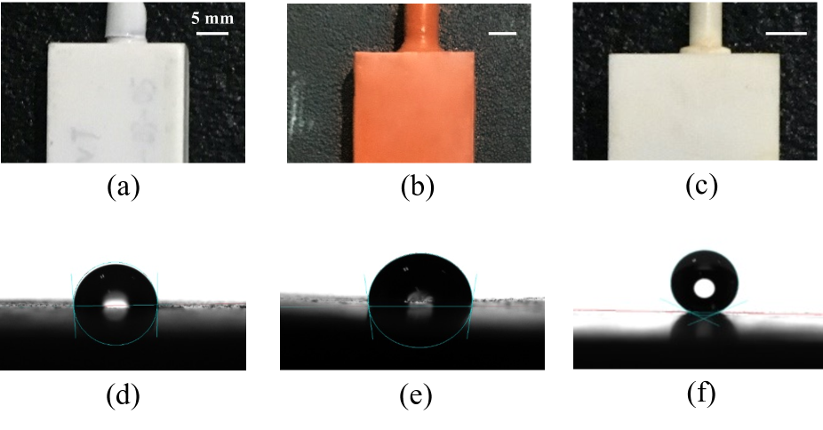
Table I shows measurement results of CAs and sliding angles of the three coatings. The SHP exhibits the largest CA and the smallest sliding angle, indicating the best hydrophobicity. Both RTV-SIR and RTV-SIFR coatings demonstrate similar CAs and relatively lower hydrophobicity.
| Coating type | RTV-SIR | RTV-SIFR | SHP |
|---|---|---|---|
| Contact angle () | 97.2 | 95.2 | 154.3 |
| Sliding angle () | 90.4 | 95.7 | 6.3 |
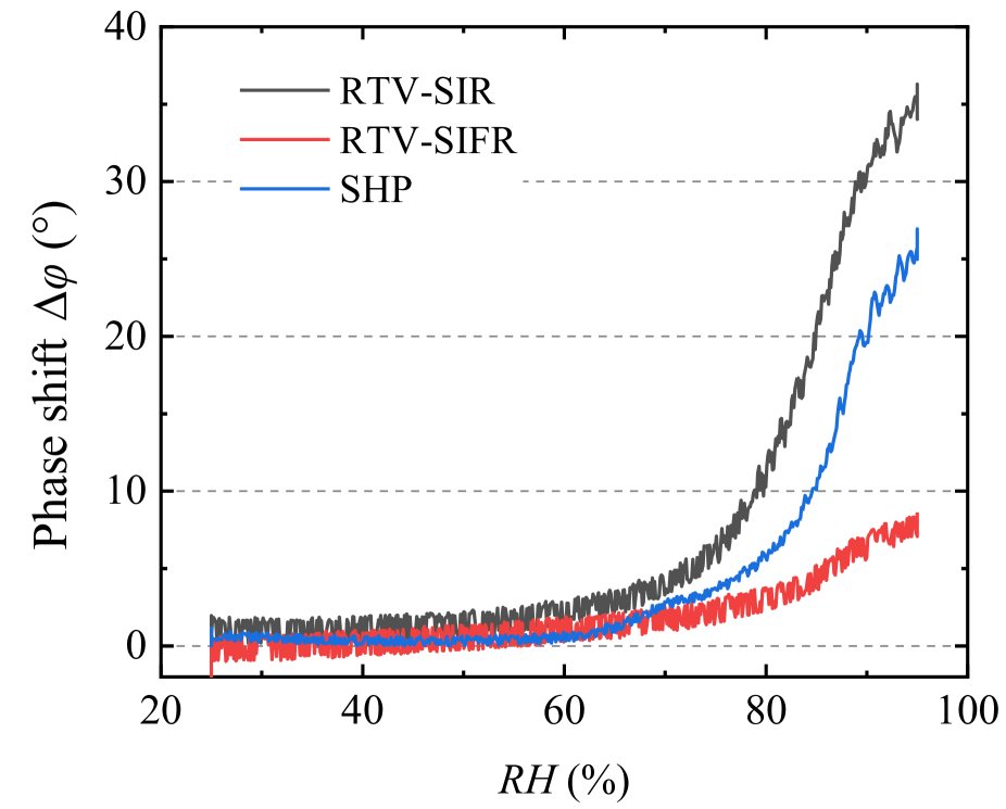
To study the humidity stability of the sensors with different HP coatings, the RH of the environmental chamber is varied from 25% to 95% at a rate of 5%/h, while maintaining a temperature of 30 C. The measured phase shifts of the three sensors with different HP coatings are shown in Fig. 6.
However, despite having the largest CA and hydrophobicity, the humidity stability of the sensor with the SHP coating is lower compared to the RTV-SIFR coating, which has the smallest CA. This indicates that the hydrophobicity of the coating is insufficient to explain the humidity stability of the sensor. Further exploration of the underlying mechanisms influencing sensor humidity stability is necessary.
III Influence Mechanisms of Humidity Stability
According to the above analysis, the hydrophobicity of the coating is not the primary factor affecting humidity stability. This section focuses on modeling and simulation of three processes: Adsorption of water vapor molecules onto the package, absorption of water vapor into the sensor shell, and adsorption of liquid water onto the package (RH 100%).
The simulation layout is shown in Fig. 7. The sensor package dimensions are 3 cm 2 cm 1 cm, representing a hollow structure with a thickness of 2 mm and filled with air. A pair of 4-cm-gap metal electrode plates are used to generate a uniform electric field. The amplitude and frequency of the voltage applied to the upper plate are 1 V and 50 Hz, while the lower plate is grounded. Water conductivity is set to be S/m, and its relative dielectric constant is 80. The conductivity of ceramic shell is 110 S/m, and its relative dielectric constant is 4.The HP coating of the sensor is ignored due to its thin thickness and low conductivity (about S/m).
Simulation models are established by the finite element method in COMSOL. The AC/DC module and transient simulation are used. The simulated sensor electric field is obtained by the probe at the center of the package (the calculation point in Fig. 7). The simulated electric field at this point is then compared with the external applied electric field between the metal plate without the sensor inside.
It should be noted that the change in the modal index of LN waveguide is not considered here. Due to LN’s non-hygroscopicity nature, its refractive index is considered to remain constant under different humidity levels. The refractive index variation of the surrounding air is within 110 due to different humidity levels [28]. Additionally, the ratio of optical mode distribution in the air cladding is very small according to Fig. 1(b).

III-A Adsorption of vapor molecules onto the sensor shell
When the RH is lower than 100%, there is only water vapor exists in the ambient environment. Based on the multimolecular layer adsorption theory from [29], areas without interaction on the shell surface begin adsorbing vapor molecules from the air by van der Waals forces, forming a monolayer of vapor molecule. Moreover, the van der Waals force between the monolayer and free vapor molecules, along with the long-range gravity between the shell’s molecules and the vapor molecules, further promotes the adsorption of vapor molecules, resulting in the formation of a multilayer vapor molecule on the shell surface [30]. The process of vapor film formation is shown in Fig. 8.
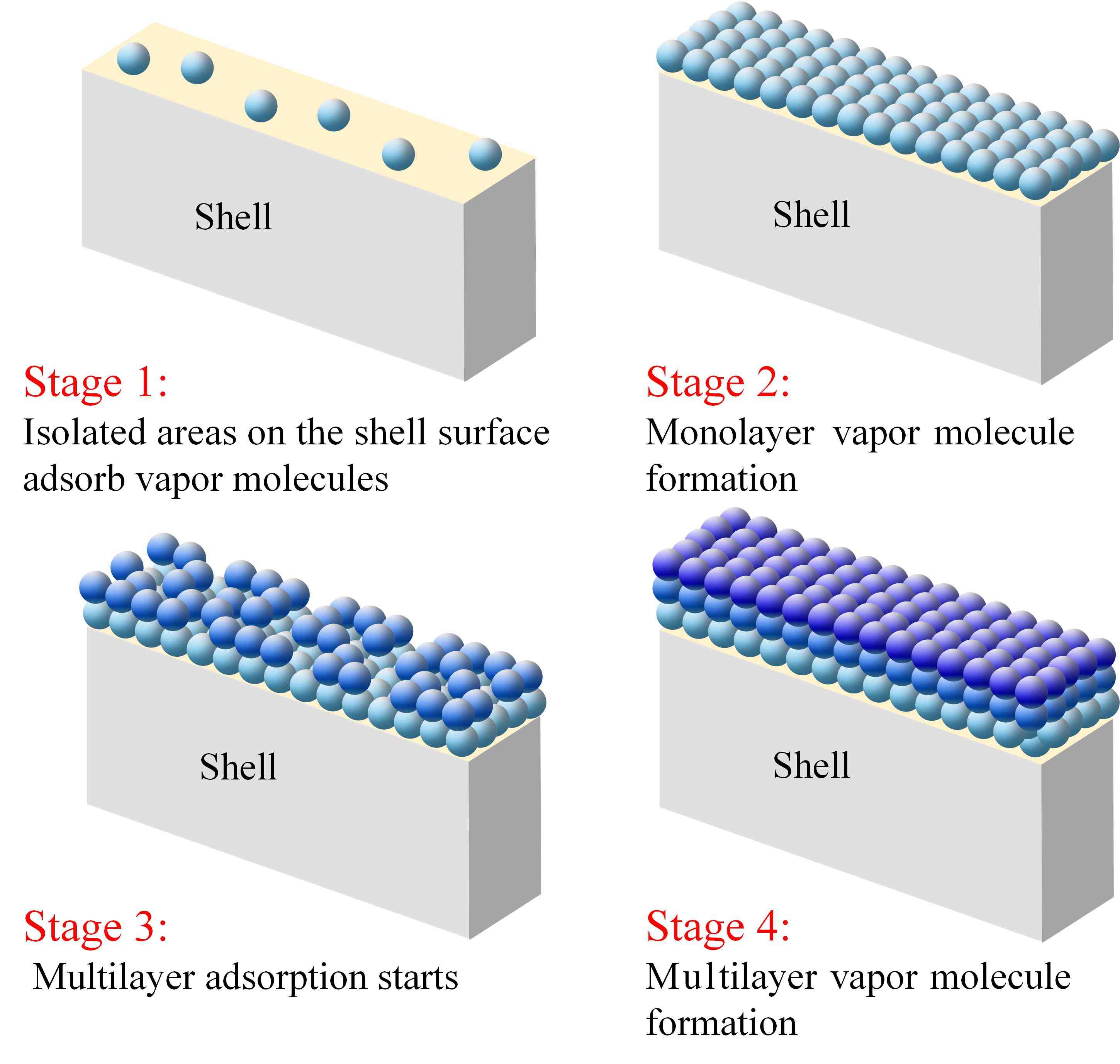
In the process, vapor molecules are adsorbed onto the shell surface by van der Waals forces, but are also desorbed due to intermolecular collisions. When the adsorption balances the desorption, the shell’s coverage is complete. Consequently, the adsorbed vapor molecules on the shell surface exist in dynamic equilibrium [31], and the film thickness is determined by substrate properties, ambient RH, and temperature [32].
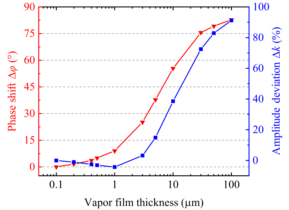
In order to study the influence of the vapor film thickness on the humidity stability of the sensor, the sensor model shown in Fig. 7 with different thicknesses of vapor film on the shell is established. The dielectric constant of vapor film is set to be 1. The simulated relationship between the sensor output and the external applied electric field, considering different vapor film thicknesses, is shown in Fig. 9. The phase shift and amplitude deviation of the sensor output gradually increase with the vapor film thickness. When the vapor film thickness is greater than 100 nm, and are 83 and 90%, respectively. However, measurement results in [33] and [34] show that the thickness of the vapor film on the solid surface is generally less than 10 nm under RH = 90%. Therefore, the adsorption of water vapor molecules onto the sensor package followed by the vapor film formation has little impact on the humidity stability of the sensor.
III-B Absorption of vapor into the sensor shell
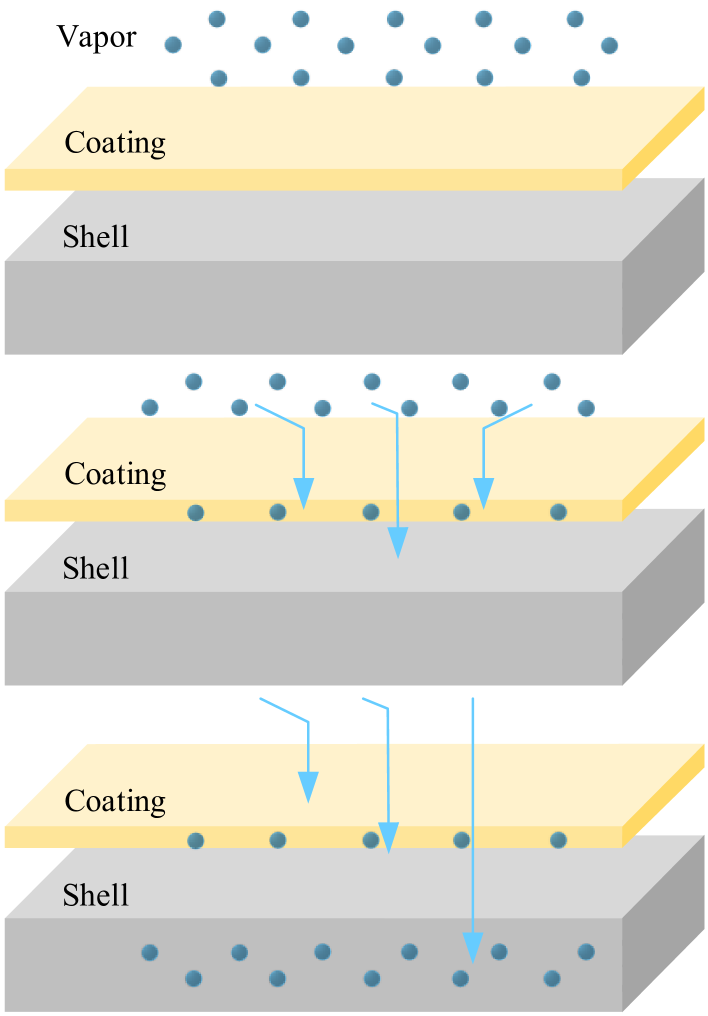
Both the HP coating and the shell material of the sensor possess certain hygroscopicity and moisture permeability [35]. The tiny pores within the HP material absorb vapor molecules from the air through capillary action. Moreover, due to the potentially higher hygroscopicity of the shell material, a substantial amount of vapor molecules within the HP material will diffuse and dissolve into the shell material [36]. The process of the shell absorbing vapor molecules is shown in Fig. 10.
As the RH increases, the absorption of water vapor by the shell also increases, resulting in an increase in the conductivity [37], [38]. The process is simulated by varying the conductivity of the shell material. The simulated relationship between humidity stability of the sensor and conductivity of the shell is shown in Fig. 11.
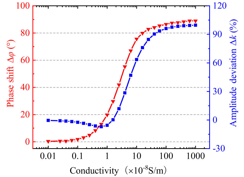
When the conductivity of shell material exceeds 110 S/m, the phase shift and the amplitude deviation of the sensor increase rapidly. When the shell conductivity increases to 110 S/m, the phase shift and the amplitude deviation gradually increase to saturation, which are 90 and 100%, respectively.
Therefore, the humidity stability of the coated sensor is significantly influenced by both hygroscopicity of the shell material and the moisture permeability of the HP coating. The results in Fig. 6 which shows the best humidity stability of RTV-SIFR coating may because of its low porosity and moisture permeability.
III-C Adsorption of liquid water onto the package
Once the RH surpasses the saturated vapor pressure of air, (i.e., RH 100%), the water vapor molecules condense into visible liquid water and are adsorbed onto the shell surface.
The morphology of water droplets on different HP shell surfaces is observed with a metallurgical microscope and modeled in COMSOL, as shown in Fig. 12. Fig. 12(a)-(c) represent the water droplet morphology on the surface of ceramic shell (CA 90), RTV-SIFR (CA = 90), and SHP (CA 150), respectively. Fig. 12(d)-(f) show the respective water droplet models in COMSOL.

When the CA is less than 90, liquid water on the shell surface forms a visible water film that connects the upper and bottom surfaces of the sensor shell, as shown in Fig. 12(a) and (d). Conversely, when the CA is approximately 90, liquid water adheres to the shell surface in the form of separate water droplets, as shown in Fig. 12(b) and (e). As the CA increases, the contact area between the water droplets and the shell reduces, resulting in smaller water droplets remaining on the shell surface, as shown in Fig. 12(c) and (f).
The simulation models use spheres with equivalent size and conductivity to microscopic water droplets. The simulated electric field output of the sensors with different degrees of shell hydrophobicity are shown in Fig. 13.
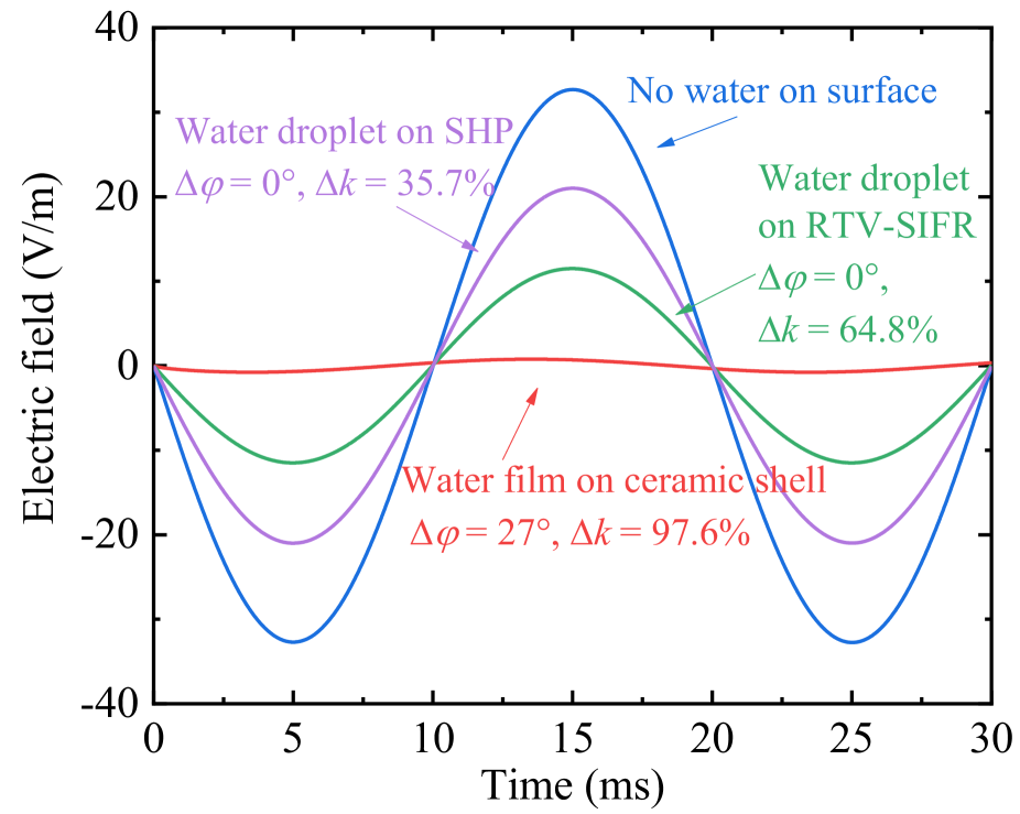
As shown by the red curve in Fig. 13, when the shell is hydrophilic, the amplitude deviation approaches 100% and the phase shift is significant. This is because the water film on the shell connects the upper and bottom surfaces of the sensor shell, forming a conductive surface along the applied field, which exhibits a shielding effect. When the CA of the shell exceeds 90, such as with RTV-SIFR and SHP coatings, the phase shifts become nearly 0 since the separate water droplets on the shell disrupt the conductive path. However, is still influenced due to some degrees of the shielding effect. Comparing the RTV-SIFR and SHP coatings, the SHP coating has a smaller contact area between the shell and water droplets, resulting in lower surface conductivity of the shell. Consequently, the amplitude deviation is smaller, as shown by the green and purple curves in Fig. 13.
Therefore, when the RH surpasses the saturated vapor pressure of air and liquid water exists in the environment, the CA and hydrophobicity of the coating influence the humidity stability of the sensor by shielding effect. A larger CA of the coating corresponds to better humidity stability.
IV Humidity Stability Improvement and Discussion
Based on the above analysis, a shell material with low hygroscopicity, poly-ether-ether-ketone (PEEK), is chosen as an alternative shell material besides ceramics. The material has low dielectric constant and relatively small thermal expansion coefficient. The characteristics of the two shell materials, PEEK and ceramic, are listed in Table II.
| Material type | PEEK | Ceramic |
|---|---|---|
| Conductivity (S/cm) | 3 | 8 |
| Relative dielectric constant | 3.2 | 4 |
| Coefficient of thermal expansion (ppm/C) | 25-50 | 3-5 |
| Hygroscopicity | Low | High |
For the ceramic materials with high hygroscopicity [39], the conductivity increases by orders of magnitude with the increase of RH. Conversely, PEEK material with low hygroscopicity [40], exhibit relatively minor variations in conductivity over a wide range of RH [37].
Four sensors were fabricated and tested: an uncoated sensor with ceramic shell, an RTV-SIFR coated sensor with ceramic shell, an uncoated sensor with PEEK shell and an RTV-SIFR coated sensor with PEEK shell. The experiment conditions are consistent with those depicted in Fig. 6, and the measured results are shown in Fig. 14.
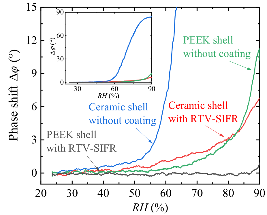
For the two sensors packaged without coating (black and green curves in Fig. 14), the humidity stability of sensor with ceramic package is found to be inferior to that of the sensor with PEEK package. The sensor with PEEK package and RTV-SIFR coating (gray curve in Fig. 14) has the most superior humidity stability, with phase shift remaining within in 1 across the RH range of 25% to 90% and at the temperature of 30 C.
To further investigate the long-term humidity stability of the sensor, the proposed packaging scheme is subjected to testing in a high humidity environment (RH = 90%, T = 30 C) for about 20 hours. A comparison is made with the sensor packaged with ceramic shell and RTV-SIFR coating. The measured results are shown in Fig. 15.
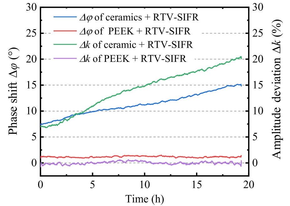
For the sensor packaged with ceramic shell and RTV-SIFR coating, the strong hygroscopicity nature of the ceramic material causes an increasing number of vapor molecules to dissolve into the shell through the HP coating, resulting in the noticeable and continuous increase of the amplitude deviation and phase shift of the sensor as the duration extends. and increase to 20% and 15 at 20 h, respectively.
However, the combination of low hygroscopicity of PEEK material with low moisture permeability of RTV-SIFR coating results in and remaining close to zero and stable over time, as shown by the red and purple curves in the Fig. 15. The slight phase shift of about 1 is attributed to the HP material absorbing a minor amount of water vapor under the relatively high humidity (RH = 90%).
Humidity stability is mainly influenced by the packaging scheme rather than the change in LN waveguide. When RH increases, the sensor shell conductivity increases because of water vapor absorption. The IOES shell has its resistance and capacitance, which form a parallel resistor-capacitor (RC) network with the LN waveguide’s resistance and capacitance. An increase in sensor shell conductivity results in a decreased resistance in the RC network, which further results in a decreased output amplitude and an increased phase shift in the sensor. The humidity-stable packaging scheme proposed here uses PEEK shell, which has moisture permeability, with room temperature vulcanized fluorinated silicone rubber (RT-SIFR) coating, which has low hygroscopicity.
Considering the outdoor application environment for sensors, both high RH and the presence of liquid water are likely to occur. Therefore, it is proposed that the RTV-SIFR and SHP coatings could be used together, with the SHP coating as the outmost layer to prevent liquid water. The packaging scheme has the potential to improve the humidity stability of other outdoor integrated sensors as well.
V Conclusion
The paper studies the influence mechanisms on the humidity stability of the integrated optical electric field sensor. It reveals that the hydrophobicity of the sensor shell only affects the humidity stability when there is liquid water on the shell surface. In environments where only water vapor is present, the hydrophobicity of the shell and the thickness of vapor film have no obvious impact on the humidity stability. Instead, the hygroscopicity of the shell and the moisture permeability of the coating play vital roles in the humidity stability. This clarification corrects the misunderstanding that the hydrophobicity of sensor shell alone determines the humidity stability of the sensor.
An optimal packaging scheme is proposed, featuring a combination of the low hygroscopicity shell material PEEK and the low moisture permeability HP coating RTV-SIFR. The sensor with the proposed packaging scheme demonstrates phase shifts consistently within in 1 across the RH range of 25% to 90% at 30 C. The long-term humidity stability shows an improvement in amplitude deviation of the electric field measurement from 20% to nearly zero after 20 hours in a high humidity environment (RH = 90%, T = 30 C). A double-layer coating with SHP besides the RTV-SIFR material could be used to resist liquid water as well. The proposed packaging scheme could also be extended to improve the humidity stability of other outdoor integrated sensors.
References
- [1] R. Zeng, B. Wang, B. Niu, and Z. Yu, “Development and application of integrated optical sensors for intense e-field measurement,” Sensors, vol. 12, no. 8, pp. 11 406–11 434, 2012.
- [2] R. Zeng, Y. Zhang, W. Chen, and B. Zhang, “Measurement of electric field distribution along composite insulators by integrated optical electric field sensor,” IEEE Transactions on Dielectrics and Electrical Insulation, vol. 15, no. 1, pp. 302–310, 2008.
- [3] H. Wang, C. Zhuang, R. Zeng, S. Xie, and J. He, “Transient voltage measurements for overhead transmission lines and substations by metal-free and contactless integrated electro-optic field sensors,” IEEE Transactions on Industrial Electronics, vol. 66, no. 1, pp. 571–579, 2018.
- [4] R. Zeng, B. Wang, Z. Yu, and H. Li, “Application of an integrated electro-optic sensor for measuring very fast overvoltages in gis,” in Proceedings of the Eleventh International Symposium on High Voltage Engineering, 2009.
- [5] Z. Li, H. Yuan, Y. Cui, Z. Ding, and L. Zhao, “Measurement of distorted power-frequency electric field with integrated optical sensor,” IEEE Transactions on Instrumentation and Measurement, vol. 68, no. 4, pp. 1132–1139, 2018.
- [6] X. Fan, W. Chen, C. Guo, Z. Wu, Z. Pei, and Q. Zhang, “Sensitivity characteristics of electro-optical sensors under ac/dc hybrid electric fields in oil medium environment,” IEEE Transactions on Instrumentation and Measurement, vol. 70, pp. 1–12, 2021.
- [7] Y. Shi, W. Wang, Z. Zhu, J. Yang, X. Nie, and Y. Cheng, “A bias controllable birefringence modulation measurement system for subnanosecond pulsed electric field,” IEEE Transactions on Instrumentation and Measurement, vol. 70, pp. 1–11, 2021.
- [8] J. Zhang, X. Wang, and Y. Zhang, “LiNbO crystal intense electric field sensor coupled with twisted polarization maintaining fiber,” IEEE Transactions on Instrumentation and Measurement, vol. 72, p. 7005110, 2023.
- [9] D.-J. Lee, Y.-P. Hong, I.-J. Hwang, and T.-W. Kang, “Integrated electro-optic sensor for intense electromagnetic pulse measurements,” IEEE Transactions on Instrumentation and Measurement, vol. 72, p. 7004608, 2023.
- [10] C. Gutiérrez-Martínez and J. Santos-Aguilar, “Electric field sensing scheme based on matched LiNbO electro-optic retarders,” IEEE Transactions on Instrumentation and Measurement, vol. 57, no. 7, pp. 1362–1368, 2008.
- [11] H. Nagata and J. Ichikawa, “Progress and problems in reliability of Ti: LiNbO optical intensity modulators,” Optical Engineering, vol. 34, no. 11, pp. 3284–3293, 1995.
- [12] X. Ma, C. Zhuang, R. Zeng, and W. Zhou, “Large-dynamic-range athermal lithium niobite on insulator/tio2 nanobeam electric field sensor,” Journal of Physics D: Applied Physics, vol. 54, no. 10, p. 105101, 2020.
- [13] H. Wang, R. Zeng, and C. Zhuang, “Thermal variation of electric field sensor bias caused by anisotropy of linbo3,” Applied Physics Letters, vol. 114, no. 14, 2019.
- [14] X. Li, X. Hai, G. Yao, Y. Cui, Y. Xi, and P. Li, “Temperature-insensitive integrated optical electric field sensor based on asymmetric mach–zehnder interferometer,” IEEE Sensors Journal, vol. 23, no. 7, pp. 6963–6968, 2023.
- [15] K. Preston, B. Macdonald, R. Harmon, C. Ford, R. Shaw, I. Reid, J. Davidson, A. Beaumont, and R. Booth, “High performance hermetic package for linbo/sub 3/electro-optic waveguide devices,” in IEE Colloquium on Integrated Optics. IET, 1989, pp. 2–1.
- [16] R. Moyer, R. Grencavich, F. F. Judd, R. C. Kershner, W. J. Minford, and R. W. Smith, “Design and qualification of hermetically packaged lithium niobate optical modulator,” IEEE Transactions on Components, Packaging, and Manufacturing Technology: Part B, vol. 21, no. 2, pp. 130–135, 1998.
- [17] B. Johnson and V. Verma, “Reliability assessment of fielded plastic and hermetically packaged microelectronics,” IEEE transactions on reliability, vol. 45, no. 1, pp. 23–26, 1996.
- [18] L. Huan, “Theoretical modeling and improvement on electro-optical integrated electric field sensor,” Ph.D. dissertation, Master dissertation, Tsinghua university, Beijing, 50-63, 2009.
- [19] C. Li, R. Zeng, B. Niu, and G. Jin, “Improvement of humidity stability for optoelectronic electric field sensor,” in 2013 International Conference on Optical Instruments and Technology: Optical Sensors and Applications, vol. 9044. SPIE, 2013, pp. 351–356.
- [20] X. Fan, S. Lee, and Q. Han, “Experimental investigations and model study of moisture behaviors in polymeric materials,” Microelectronics Reliability, vol. 49, no. 8, pp. 861–871, 2009.
- [21] G. Momen, M. Farzaneh, and R. Jafari, “Wettability behaviour of rtv silicone rubber coated on nanostructured aluminium surface,” Applied Surface Science, vol. 257, no. 15, pp. 6489–6493, 2011.
- [22] Z. Wang, Z. Jia, M. Fang, Y. Li, and Z. Guan, “Moisture absorption, desorption, and moisture-induced electrical performances of high-temperature vulcanized silicone rubber,” IEEE Transactions on Dielectrics and Electrical Insulation, vol. 23, no. 1, pp. 410–417, 2016.
- [23] M. Shirangi and B. Michel, “Mechanism of moisture diffusion, hygroscopic swelling, and adhesion degradation in epoxy molding compounds,” Moisture sensitivity of plastic packages of IC Devices, pp. 29–69, 2010.
- [24] D. Bond and P. Smith, “Modeling the transport of low-molecular-weight penetrants within polymer matrix composites,” Applied Mechanics Reviews, vol. 59, no. 1-6, pp. 249–268, 2006.
- [25] R. L. Shook, T. R. Conrad, V. S. Sastry, and D. B. Steele, “Diffusion model to derate moisture sensitive surface mount ic’s for factory use conditions,” IEEE Transactions on Components, Packaging, and Manufacturing Technology: Part C, vol. 19, no. 2, pp. 110–118, 1996.
- [26] J. Christie, S. Krenek, and I. Woodhead, “The electrical properties of hygroscopic solids,” Biosystems engineering, vol. 102, no. 2, pp. 143–152, 2009.
- [27] Y. Qing, S. Shi, C. Lv, and Q. Zheng, “Microskeleton-nanofiller composite with mechanical super-robust superhydrophobicity against abrasion and impact,” Advanced Functional Materials, vol. 30, no. 39, p. 1910665, 2020.
- [28] R. J. Mathar, “Refractive index of humid air in the infrared: model fits,” Journal of Optics A: Pure and Applied Optics, vol. 9, no. 5, p. 470, 2007.
- [29] S. Brunauer, P. H. Emmett, and E. Teller, “Adsorption of gases in multimolecular layers,” Journal of the American chemical society, vol. 60, no. 2, pp. 309–319, 1938.
- [30] T. Horikawa, D. Do, and D. Nicholson, “Capillary condensation of adsorbates in porous materials,” Advances in colloid and interface science, vol. 169, no. 1, pp. 40–58, 2011.
- [31] G. Fagerlund, “Determination of specific surface by the bet method,” Matériaux et Construction, vol. 6, pp. 239–245, 1973.
- [32] G. E. Ewing, “Ambient thin film water on insulator surfaces,” Chemical reviews, vol. 106, no. 4, pp. 1511–1526, 2006.
- [33] R. Badmann, N. Stockhausen, and M. J. Setzer, “The statistical thickness and the chemical potential of adsorbed water films,” Journal of Colloid and Interface science, vol. 82, no. 2, pp. 534–542, 1981.
- [34] G. Zhao, Q. Tan, L. Xiang, D. Cai, H. Zeng, H. Yi, Z. Ni, and Y. Chen, “Structure and properties of water film adsorbed on mica surfaces,” The Journal of chemical physics, vol. 143, no. 10, 2015.
- [35] C. Chen, Z. Jia, H. Lu, Z. Yang, and T. Li, “Field aging investigation and filler precipitation analysis on rtv coated insulators in china,” IEEE Transactions on Dielectrics and Electrical Insulation, vol. 21, no. 6, pp. 2458–2465, 2014.
- [36] Z. Harun, T. C. Ong, and R. Ahmad, “Drying comparison of nonhygroscopic and hygroscopic materials,” Applied Mechanics and Materials, vol. 465, pp. 637–641, 2014.
- [37] K. Ogura, A. Fujii, H. Shiigi, M. Nakayama, and T. Tonosaki, “Effect of hygroscopicity of insulating unit of polymer composites on their response to relative humidity,” Journal of The Electrochemical Society, vol. 147, no. 3, p. 1105, 2000.
- [38] Y. Awakuni and J. Calderwood, “Water vapour adsorption and surface conductivity in solids,” Journal of Physics D: Applied Physics, vol. 5, no. 5, p. 1038, 1972.
- [39] T. Kato, K. Ohashi, M. Fuji, and M. Takahashi, “Water absorption and retention of porous ceramics fabricated by waste resources,” Journal- Ceramic Society Japan, vol. 116, no. 1350, pp. 212–215, 2008.
- [40] G. Baschek, G. Hartwig, and F. Zahradnik, “Effect of water absorption in polymers at low and high temperatures,” Polymer, vol. 40, no. 12, pp. 3433–3441, 1999.