|
Polylines |

  
|
|
Polylines |
|
Polyline data consists of a series of points (vertices) connected by lines. Polyline data objects can be used in VMOD Flex for defining geometry and assigning attributes to linear boundary conditions, such as River and Drain boundary conditions. Polylines may also be useful to visualizing geographic features such as river and road networks.
VMOD Flex supports the following file types for polyline data.
| · | Shapefile, *.SHP |
| · | AutoCAD, *.DXF |
To import polyline data, follow the steps below:
| · | Right-click in the Data Explorer, and select Import Data... from the pop-up menu. |
| · | Select Polyline from the Data Type drop down list. |
| · | Click the [...] button and locate the source file. |
| · | Enter a Name and a Description and then click [Next] to continue. |
The next step involves selecting the coordinate system of the source file, and will vary depending on which file-type is selected for the source file.
For .SHP files, if the associated .PRJ file is located in the same location as the source file, VMOD Flex can automatically detect the coordinate system of the source data and will perform a geotransformation if the coordinate system is different than that defined in the project settings. If a .PRJ file is missing, than you will be prompted to select the Coordinate System for the data being imported.
For .DXF files. you will always be prompted to select the Coordinate System of the selected source file.
Click the [Next] button to continue.
If the file type is .SHP, the next step involves creating attributes. If you are importing from .DXF file, you can skip this step.
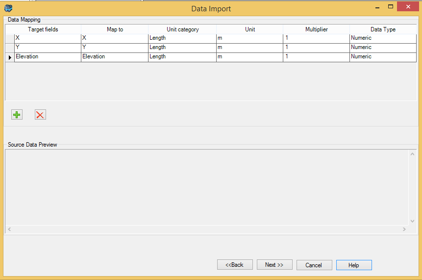
If the file you are trying to import is a 3D Shapefile (with Elevation defined), then VMOD Flex should automatically detect this, and you should not need to map the Elevation attribute at this step.
This dialog allows you to import shapefile attributes. To create a new attribute, click the Add a new attribute button. When selected, a new row will be added to the Data Mapping table.
In the Map_to column, select the desired attribute field in the source data, from the combo box. Repeat for additional attributes. You can delete a mapped attribute by selecting the row from the Data Mapping table, and then clicking the Delete button.
For a description of the Unit Category, Unit, Multiplier and Data Type columns, please refer to section "Data Mapping" section.
Click the [Next] button to continue.
The final step involves validation of the data being imported. This step will ensure that the data set contains valid data for each of the mapped columns.
For .SHP files, please refer to "Data Validation" section for more information on the data validation step.
For .DXF files, the following dialog will show, indicating the number of polylines that will be created from the source file.
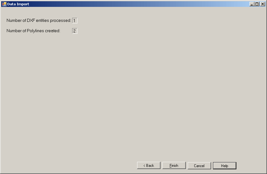
Click the [Finish] button to complete the polygon importing process. Once imported, a polyline data object will be added to the Data Explorer.