|
Cross Sections |

  
|
|
Cross Sections |
|
The following section describes the available style settings for cross section data objects.
To access the style settings, right-click on the cross section data object in the Data Explorer, and select Settings... from the pop-up menu. Then, in the Settings dialog, expand the Style node to view the style settings.
Cross section data objects consist of two main elements; the interpretation layers and the cross section wells. The settings for each element can be accessed by clicking on the Interpretation or Wells node, respectively.
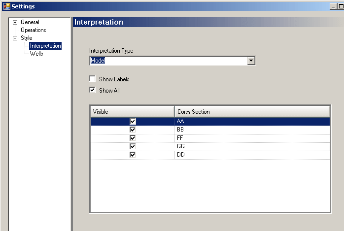
Interpretation
A screen capture of the interpretation settings is shown above.
From the Interpretation Type combo box, select which interpretation layer to show in 3D Viewer. Select from Model, Geology or Hydrogeology.
When a interpretation layer is selected from the combo box, its associated cross sections are listed in the grid below. Under the Visible column, select which cross section to show/hide in 3D Viewer.
Select the Show All check box to show all the cross sections for the selected interpretation layer.
Select the Show Labels check box to show the label for each cross-section.
Wells
The wells node contains settings for changing the appearance of the cross section wells. These settings are described below.
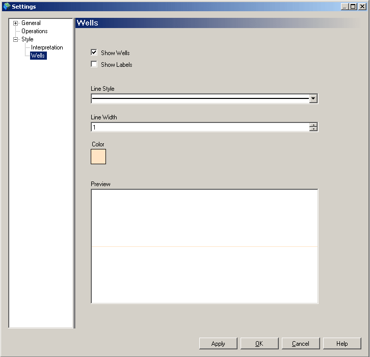
Show Wells: Check this option to show the well geometry.
Show Labels: Check this option to show the well label above each well.
Line Style: Select the type of line to display. Choose between solid or dashed.
Line Width: Specify the width of the wells.
Color: Change the color of the wells.
Click the [Apply] button to display the changes in an active 3D Viewer window.