Navigation:  »No topics above this level«

Program Overview

Print this Topic Previous pageReturn to chapter overviewNext page
Show/Hide Hidden Text

In order to become the most efficient and effective in the VMOD Flex environment, it is recommended that you familiarize yourself with a few simple concepts, terminology, and where you can find and access things.


Click to expand/collapseData Objects

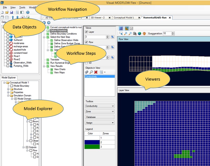
All of the data that you interact with in VMOD Flex are referred to as data objects.  These can consist of:


·Raw Data that you have
·Imported: From polyline or polygon shapefiles, wells from a spreadsheet, surfaces from Surfer .GRD, etc.
·Created: Through digitizing points, polygon, or polylines
·Conceptual Data Objects: These are generated as you progress through the conceptual modeling workflow, and include:
·Horizons, Structural Zones, Property Zones, and Boundary Conditions.
·Numerical Model Data Objects. These are generated as you progress through a numerical modeling workflow, and include:
·Input: Numerical Grid, Properties (Conductivity, Initial Heads, etc..), Boundary Conditions (a group of river cells, drain cells, pumping  well cells, etc..), Observation Wells, Zone Budget zones, and Particles.
·Output: Calculated Heads, Drawdown, Pathlines, etc.

Each data object will have a check box beside it, allowing it to be displayed in different 2D/3D viewers.


Each data object also has Settings which can be accessed by right clicking on the data object in the tree, and selecting Settings.  The settings provide access to general properties (statistics, file origin, etc.) and Style settings (symbol colors, shape, labeling, etc.). For more details, see Data Settings


Many wizards and dialog boxes in VMOD Flex require you to select data objects from the Data Explorer or Conceptual Model Explorer, e.g., when defining horizons, creating property zones, and assigning attributes to boundary conditions.

When you see a  Blue Arrow located next to an input field in a dialog box or a wizard, this means that a data object selection is required. Simply click the appropriate data object from the Data Explorer or Conceptual Model Explorer and then click the Blue Arrow button to insert the data object into the input field.

Click to expand/collapseModel Explorers

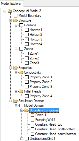
The Model explorers contain all of the conceptual models and numerical models, and corresponding data objects for your project.


Conceptual Model Tree

Numerical Model Tree


Click to expand/collapse2D/3D Viewers

Data objects can be displayed in one or more of the following viewers:


·2D View: Plan view; ideal for GIS data, surfaces, well locations, images, etc.
·3D View: Ideal for data that have X,Y and Elevation (Z) values defined: Structural Zones, Wells, Pathlines, Heads along a cross-section, etc.
·The "Flex" Viewer: which is available in the numerical modeling workflow, and consists of a combination of a Layer, Row and Column view and 3D View; the individual views can be shown/hidden.
Click to expand/collapseWorkflows

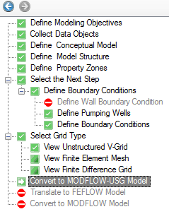
Groundwater modeling consists of a series of steps that must be completed in a particular sequence in order to achieve a specific goal. In VMOD Flex, these steps are presented in a workflow. In  the Workflow window, you see the steps that make up a workflow and at each step there is a corresponding GUI with which you interact. The benefits to you as a modeler are unlimited:


·Simplicity: You know where you are and where you have to go. This dramatically reduces the learning curve
·Accessibility: all the actions you need are available at your fingertips; no more hunting for an option deep inside a menu.
·Convenience: modeling is iterative and requires a frequent amount of flipping between input, run, and results. The workflow GUI simplifies these back-and-forths.

In VMOD Flex, there is a workflow for Numerical Modeling and a workflow for Conceptual Modeling.


The workflow panel contains a toolbar and a list of steps required for your current workflow.


Navigating a Workflow


Go to the Previous Step in the workflow

Go to the Next Step in the workflow


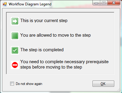
Workflow States

Beside each state in the workflow there is a corresponding icon. The icon helps you to identify which is your current step, which steps have been completed, and which steps you may proceed to next.  The image below provides an explanation of this.