|
Converting to MODFLOW-USG |

  
|
|
Converting to MODFLOW-USG |
|
Quick Overview
Instructions |
Create a MODFLOW-USG numerical model by populating the selected grid with data from the conceptual model |
Pre-requisites: |
An UnStructured Grid has been created.
|
Result: |
A numerical model is generated and added to the Model Explorer tree. The numerical model workflow will appear. |
Next Steps: |
Once you have the conceptual model designed and at least one UnStructured grid, you are ready to populate this grid with the conceptual data.
Proceed to the "Convert to MODFLOW-USG Model" step in the Conceptual Model workflow; this is shown in the display below.
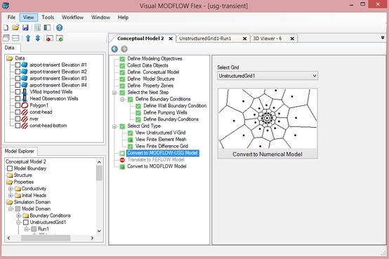
The Select Grid combo box will list all the UnStructured grids you have created for your project
Select the grid you wish to use ,and click on the "Convert to Numerical Model" button.
|
This conversion process could take several minutes, depending on the number of cells in the grid, the number of layers, and the complexity of the conceptual model inputs. Please be patient. |
After the conversion is complete, a new numerical model workflow window will appear which includes the steps for viewing and editing the UnStructured grid numerical model.
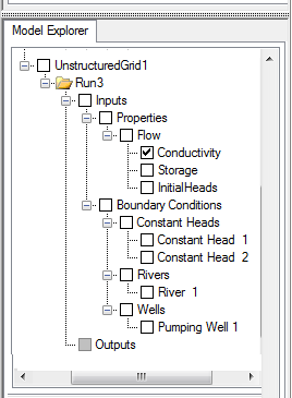
During the conversion, a "Run" node will be added to the Model Explorer under the UnStructured grid that you selected. This Model Explorer tree will be populated with all the inputs from your conceptual model: Properties, Boundary Conditions, Wells, etc.
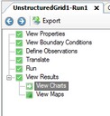
When the conversion is complete, you can click on the ![]() Next button on the workflow toolbar, which will take you to the View/Edit Properties. You can then proceed through the MODFLOW-USG numerical model workflow.
Next button on the workflow toolbar, which will take you to the View/Edit Properties. You can then proceed through the MODFLOW-USG numerical model workflow.