|
Converting to MODFLOW-2000/2005 (Structured Grid) Numerical Model |

  
|
|
Converting to MODFLOW-2000/2005 (Structured Grid) Numerical Model |
|
Quick Overview
Instructions |
Create a MODFLOW numerical model by populating the selected grid with data from the conceptual model |
Pre-requisites: |
Finite Difference Grid has been created.
|
Result: |
A numerical model is generated and added to the Model Explorer tree. The numerical model workflow will appear. |
Next Steps: |
Once you have the conceptual model designed and at least one numerical grid, you are ready to populate this grid with the conceptual data.
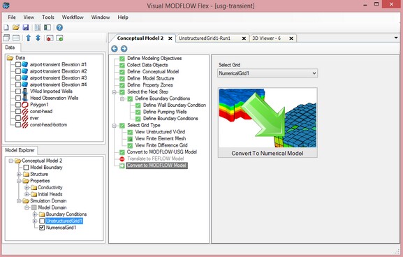
Proceed to the "Convert to Numerical Model" step in the Conceptual Model workflow; this is shown in the display below.
The Select Grid combo box will list all the finite difference grids you have created for your project, including grids for use in Local Grid Refinement (LGR)
Select the grid you wish to use ,and click on the "Convert to Numerical Model" button.
(Alternatively, you can select the desired numerical grid from the Model Explorer tree, right mouse click, and select "Convert to Numerical Model from the pop-up menu..)
After clicking on the conversion button, a new numerical model workflow window will appear which includes the steps for the numerical model. In the first window, you will see the progress of the conceptual to numerical conversion. This conversion could take several minutes, depending on the size and type of grid you used, and the complexity of the conceptual model inputs.
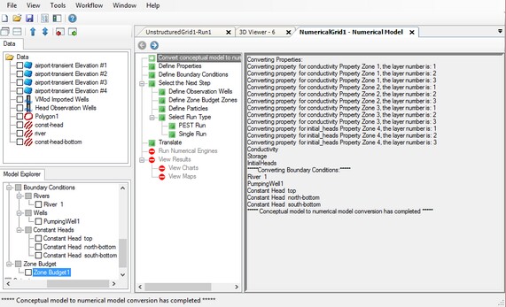
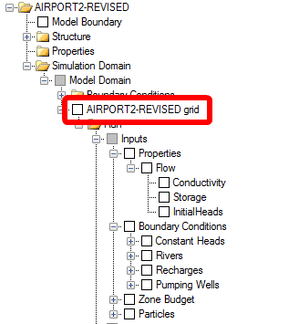
During the conversion, the run node will be added to the model explorer under the numerical grid that you selected. This tree will be populated with all the inputs from your conceptual model: Properties, Boundary Conditions, Wells, etc.
When the conversion is complete, you can click on the ![]() Next button on the workflow toolbar, which will take you to the Define Properties. You can then proceed through the numerical model workflow.
Next button on the workflow toolbar, which will take you to the Define Properties. You can then proceed through the numerical model workflow.
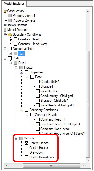
Converting MODFLOW Grids with Child Grids
When you convert a Grid that contains one or more child grids (for an LGR run), the inputs on the Model Explorer tree will contain objects for the parent model and each child model.
In the example below, Conductivity1, Storage1, InitialHeads1 are the property values for the Parent Grid.
Conductivity-Child grid1, Storage - Child grid1, and InitialHeads - Child grid 1 are the property values for ChildGrid1.
The same convention applies for boundary condition cells: there is one entry for the parent grid boundary cells and one entry for each of the child grid cells.
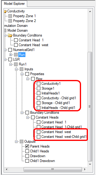
After a successful MODFLOW-LGR run, you will see multiple entries in the Output directory: Heads for the parent grid and Heads for each of the child grids, and likewise for Drawdown.