Quick Overview
Instructions |
Specify the horizontal grid resolution and the vertical layering type and resolution |
Pre-requisites: |
|
Result: |
A numerical grid is created |
Next Steps: |
From the "Select Grid Type" step in the Conceptual Model workflow, click on the "Define Finite Difference Grid button":

By default, VMOD Flex discretizes the horizontal grid using 20 rows and 20 columns, with no rotation. However, you can customize the grid to your liking, by modifying the settings in the horizontal grid dialog (shown below).
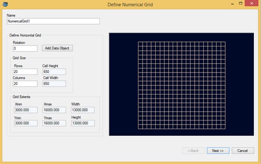
Enter a unique Name for the numerical grid. This name will appear in the Model Explorer tree once the grid is created.
The grid can be rotated counter-clockwise about the grid origin by entering a value between 0 and 360 in the Rotation text field.
The Xmin and Ymin values refer to the X-Y coordinates of the bottom-left corner of the numerical grid. The Xmax and Ymax values refer to the X-Y coordinates of the top-right corner of the numerical grid.
The Columns and Rows fields allow you to define the Grid Size. The maximum grid size supported by VMOD Flex is 5000 rows by 5000 columns.
Click the [Next] button to proceed to define the vertical discretization.
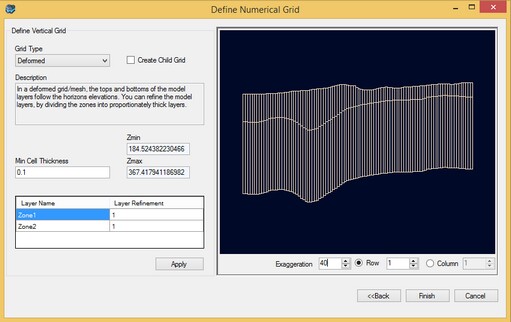
The first step in defining the vertical grid is selecting the Grid Type. There are three different grid types: Deformed, Uniform and Deformed-Uniform. Each grid type is described in the following sections.
Grid Types
Deformed
In a deformed grid, the tops and bottoms of the model layers conform to the horizons elevation. You can refine the model layers, by diving the structural zones into proportionately thick layers.
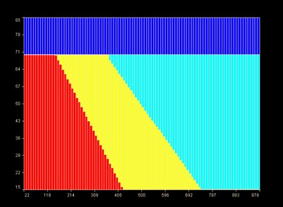
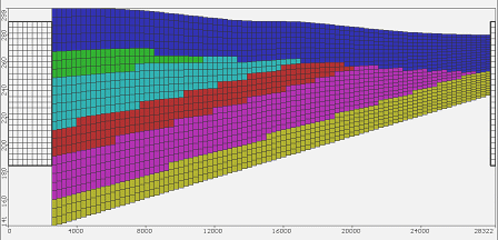
Cross sectional view of deformed grid from Visual MODFLOW Flex
A Minimum Cell Thickness must be specified as MODFLOW does not permit lateral discontinuity of layers, i.e., a layer cannot have a thickness of 0 at any point in the layer. When horizons are on-lapping one another, resulting in a zero cell thickness, the minimum cell thickness is applied and the horizons are shifted based on the horizon types defined in the Horizon settings (See "Horizon Types" section).
For deformed grids, you have the option of refining (subdividing) each layer into a specified number of equally thick layers. In the table located below the grid description, enter a refinement factor for the desired layer(s). For example, a layer refinement factor of 2 would subdivide the layer into two equally spaced layers.
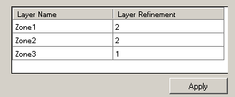
After entering a refinement factor, click the [Apply] button to view the changes in the adjacent 2D Viewer.
Uniform
In a uniform grid, a number of layers with uniform thickness will be created. At the time of translating the conceptual model to the numerical model, the properties will be assigned to the appropriate grid cells to represent the geological structure. This grid is useful for transport or density-dependent simulations, where it is desirable to have fine vertical discretization.
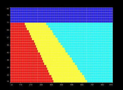
Cross sectional view of uniform grid from Visual MODFLOW
When this grid type is selected, specify the number of layers to create in the Number of Layers field (default is 10).
Note: Maximum number of vertical layers is 1000.
Deformed-Uniform
In a deformed-uniform grid, the top and bottom of the grid are deformed, following the top-most and bottom-most horizons respectively; in between, a set of uniformly thick layers will be generated. At the time of translating the conceptual model to the numerical model, the properties will be assigned to the appropriate grid cells to represent the geological structure. This grid is useful where you have discontinuous layers.
Cross sectional view of deformed-uniform grid from Visual MODFLOW
For Deformed-Uniform grids, you must specify a Minimum Cell Thickness (see above) and the Number of Layers.
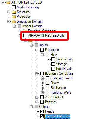
Once the grid is created, it will appear as a new node in the tree as shown below: