|
Create New Conceptual Model |

  
|
|
Create New Conceptual Model |
|
At this step, provide the conceptual model area and the start date.
Quick Overview
Instructions: |
Provide a polygon for the conceptual model area |
Pre-requisites: |
A polygon data object has been imported or created |
Result: |
Model Explorer tree is defined with the Model Boundary |
Next Steps: |
Once you have imported sufficient raw data into your project, you can begin to construct one or more conceptual models using imported or digitized data objects as building blocks. At this step, you need to define some basic information about the conceptual model, and provide a polygon that represents the model area.
You can import a polygon shapefile/DXF file, as described in the section Import Polygons
Or, if you do not have a polygon, you can create an empty polygon data object, then digitize the geometry. Please refer to the section Creating New Data Objects for more details.
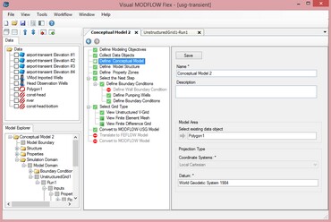
In the Define Conceptual Model window (as shown above), define the settings for the conceptual model.
| · | Enter a unique name for the conceptual model in the Name field. |
| · | Enter a description of the conceptual model in the Description field (optional). |
| · | Specify a start date from the Start Date combo box. This will be used for calculating the start date for transient model runs. NOTE: If you are using pumping wells, the start date must match the first start time for your pumping schedule. |
| · | From the Data Explorer, select the polygon data object that represents the conceptual model horizontal boundary, and then click the |
| · | Note: The model area cannot be defined using a complex polygon, or one that contains multiple polygons. A complex polygon is a polygon that intersects with itself. |
| · | Click the [Save] button. |
Once you are finished, click ![]() (Next Step) to proceed.
(Next Step) to proceed.
Model Explorer Tree
Once a conceptual model is created, a new Conceptual Model tree is added to the Model Explorer. The conceptual model tree sets up the workflow for structural and property modeling, assigning boundary conditions, numerical grid creation, and numerical model translation. A typical conceptual model tree is shown below:
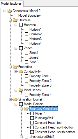
The Model Boundary node allows you to show/hide the conceptual model boundary in a 2D or 3D Viewer.
The Structure folder allows you to define the horizons and structural zones of the conceptual model. For more information on structural modeling, please see "Defining the Structure".
The Properties node allows you to define property zones for the conceptual model. For more information on property modeling, please see "Defining Property Zones".