|
Define Property Zones |

  
|
|
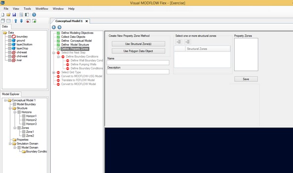
Define Property Zones |
|
At this step, define the flow property values for the geological formations.
Quick Overview
Instructions: |
Define flow properties for the conceptual model |
Pre-requisites: |
Structural Zones are created.
If you wish to use shapefiles, you have imported or digitized polygons. |
Result: |
One or more property zones are created |
Next Steps: |
At this step, you define Property Zones for the conceptual model. Each property zone is assigned appropriate property attributes, e.g., conductivity, storage, and initial heads.
A groundwater flow model requires many different types of data to simulate the hydrogeological processes influencing the flow of groundwater. In VMOD Flex, the hydrogeological characteristics of the model are classified into the following parameter groups:
| · | Conductivity (Kx, Ky, Kz) |
| · | Storage (Ss, Sy, Peff, Ptot) |
| · | Initial Heads |
By default, VMOD Flex automatically assigns the entire model domain the default property parameter values, specified in the Project Settings (see "Project Settings" for more details) . However, in most situations, the flow properties will not be uniform throughout the entire model domain, and it will be necessary to assign different property values to different areas of the conceptual model. This can be accomplished by creating Property Zones. In VMOD Flex, a property zone is a specified 3D volume, generated from structural zones, with user-defined hydrogeologic attributes.
Property zone geometry can be defined using one or more existing structural zones. As such, property zones can only be generated after horizons have been defined in the conceptual model. Please see Defining the Structure for more details.
VMOD Flex supports various methods for assigning values to hydrogeologic parameters. The method used for defining attributes can be defined on the parameter level, allowing you to use different methods for different parameters. The supported methods include:
| · | Use Constant Value |
| · | Use Surface Data Object |
| · | Use 3D Gridded Data Object |
| · | Use Shapefile |
The following sections provide information on the following topics:
| · | Defining a New Property Zone |
| · | Assigning Property Parameters |
| · | Editing Property Zones |
| · | Deleting a Property Zone |
Creating New Property Zone
|
Make sure you have imported or created all the data objects that you plan on using for properties. If you wish to use a property distribution, Import Surfaces or Create Surfaces. If you wish to use shapefiles, Import Polygons or Digitize Polygons |
Before you can create a property zone, you must have already defined horizons for the conceptual model. For more information, see Defining the Structure.
To define a new property zone, follow the steps below:
| · | Enter a Name and Description (optional) for the property zone in the Name and Description fields, respectively. |
| · | Select the method by which the property zone geometry will be defined. There are two options: Use Structural Zone(s) and Use Polygon Data Object. |
Using Structural Zone(s)
This method allows you to create a property zone from existing structural zones in your conceptual model, i.e., zones generated from horizons.
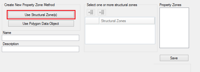
| · | Click on the [Use Structural Zone] button as shown above. |
| · | Select a zone from the Model Explorer tree (under the Zones node), and then click the |
| · | Click the |
| · | Proceed to Defining Property Zones |
This method allows you to define a property zone using both a structural zone and a polygon data object. The polygon data object is used to define the horizontal extent of the property zone and therefore must be fully contained within the conceptual model boundary. The structural zone is used to define the volume, i.e., the vertical extent of the property zone.
| · | Select a polygon data object from the Data Explorer, and click the |
| · | Note: The selected polygon cannot contain multiple parts, overlapping shapes or holes. These features are currently not supported for property zone creation. If your polygon does not meet this criteria, it can be edited using the 2D Viewer editing tools. For more information on this topic, please see "Creating New Data Objects" |
| · | Next, select a structural zone from the Model Explorer tree, and click the |
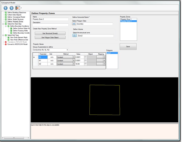
Once the geometry has been defined, you can assign parameter values to the property zone.
| · | Select the group of parameters that will be defined, e.g., conductivity, storage or initial heads. The data input grid below will display the appropriate parameters based on which parameter group is selected. For example, if conductivity is selected, the data input grid will show the parameters Kx, Ky, and Kz. The data input grid will already be populated with the default values specified in the Project Settings (File > Project Settings... ). |
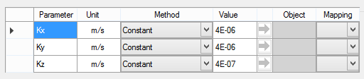
| · | VMOD Flex provides various methods for assigning parameter attributes. The available methods include: Constant Value, Use Surface, Use 3D Gridded Data and Use Shapefile (available only when property zone is defined using polygon data object). The type of method used can be specified per parameter. For each parameter in the data input grid there is a combo box in the Method row (shown below). |
Each method is described in the following sections.
Constant Value
The Constant Value method is selected by default for each parameter in the data input grid and allows you to specify a spatially constant value for the parameter. If you do not wish to use the default value, enter a new value.
Use Surface
The Use Surface method allows you use an existing surface data object to define spatially-variable attribute values. This is ideal if you have a Surfer .GRD or ESRI ASCII GRD file containing parameter values. Follow the steps below:
| · | Select "Surface" as the method from the combo box. You should then see the |
| · | From the Data Explorer, select the desired surface data object |
| · | Click the |
Note: The selected surface data object must cover the entire area of the property zone, or else the data object cannot be used.
Use 3D Gridded Data
The Use 3D Gridded Data method allows you to use an existing 3D gridded data object to define spatially-variable attribute values. Follow the steps below:
| · | Select "3D Grid" as the method from the combo box. You should then see the |
| · | From the Data Explorer, select the 3D Gridded data object |
| · | Click the |
| · | Select the desired attribute value from the "Mapping" combo box. |
Note: The specified 3D Gridded data object must horizontally and vertically overlap the defined property zone geometry, or else the data object cannot be used.
Use Shapefile Attribute
The Use Shapefile method is only available when you define the property zone geometry using a polygon data object. This method allows you to assign an attribute value using an attribute from the specified polygon data object. Follow the steps below:
| · | If you have not already done so, create the Property Zone Using Polygon Data Object, as described above. |
| · | Select the Use Shapefile Attribute from the method combo box. |
| · | Under Attribute column, the combo box contains all the attributes of the specified polygon. |
| · | Select the desired attribute from the combo box. |
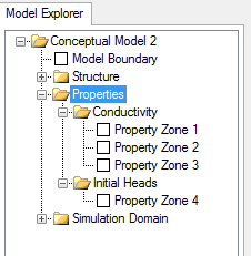
Once the property zone attributes have been defined, click the [Save] button to create the property zone. Once created, the property zone is added to the Model Explorer tree under the Properties node and under the appropriate parameter category node.
Transport Property Zones
If you need to include contaminant transport in your model, then the properties for transport will be done in the numerical workflow. Be sure that in the Define Modeling objectives step (in the Conceptual Model), that you have selected "Transport Active". After you define a numerical grid, and create a numerical model, the transport properties will be defined at the "Define Properties" step.