The Time Steps option is only available when you are running a transient model (i.e. when Transient Flow run type is selected). For transient flow simulations, VMOD Flex will automatically merge all of the different time periods defined for all of the different pumping wells and boundary conditions into the uniform stress period format required by MODFLOW. A stress period is defined as a time period in which all the stresses (boundary conditions, pumping rates, etc.) on the system are constant. Unfortunately, the data collected for each modeling site is rarely synchronized in terms of stress periods, so VMOD Flex merges the time schedules for all pumping wells and boundary conditions to determine the length of each stress period for a transient simulation. As a result, the user cannot directly modify the number of stress periods or the length of each stress period.
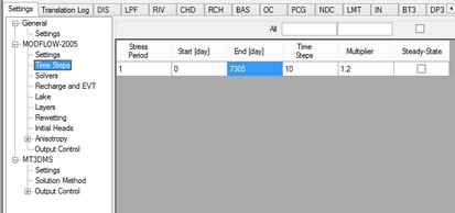
The Time step options window (as shown in the following figure) is used to define the number of Time steps in each stress period and the time step Multiplier is used to increment each time step size.
The Period # column indicates the stress period number while the Start and Stop columns indicate the start time and stop time, respectively, for each stress period.
Each stress period is divided into a user-defined number of Time steps whereby the model will calculate the head solution at each time step. The default value for Time steps is 10.
The time step Multiplier is the factor used to increment the time step size within each stress period (i.e. it is the ratio of the value of each time step to that of the preceding time step). The default value is 1.2. A time step Multiplier value greater than 1 will produce smaller time steps at the beginning of a stress period resulting in a better representation of the changes of the transient flow field. Thus increasing the number of time steps in a simulation may result in smoother head or drawdown versus time curves.
The Steady-state column indicates if the stress period is transient or steady-state. This option is available if MODFLOW-2000, MODFLOW-2005 and MODFLOW-SURFACT is selected as the numeric engine for the flow model. These engines allow individual stress periods in a single simulation to be either transient or steady state instead of requiring the entire simulation to be either steady state or transient. Steady-state and transient stress periods can occur in any order. Commonly the first stress period may be run as steady state, to produce a solution that is used as the initial condition for subsequent transient stress periods.
Accommodating Boundary Conditions with Varying End Times
VMOD Flex allows you to define boundary conditions with varying end times; the number of stress periods for the model will be calculated from the end time of the longest boundary condition. If there is a stress period where there are no data defined for a boundary condition, then you will see an entry of "0" in the appropriate package, for that stress period; this denotes that zero cells are defined for that stress period. In the case of pumping wells, you will see a rate of 0 for the well cells.