|
View Grid |

  
|
|
View Grid |
|
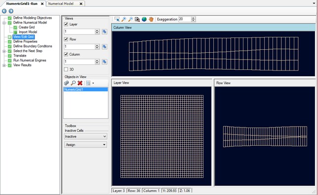
After you have created a grid or imported a grid (and associated model), you will be taken to the View/Edit Grid step. There are several options available.
| · | Under Views, select the various views you want to see in the Flex viewer; VMOD Flex allows you to simultaneously show a layer, row, column and 3D Views. |
| · | Adjust a specific layer, row, or column using the up/down arrows or enter a specific row, column, or layer integer. Alternatively, click on the |
| · | The standard navigation tools allow you to zoom, pan, and in the case of 3D view, rotate. |
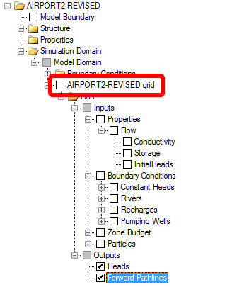
The numerical grid will appear as a node in the model tree, as highlighted in red.
You can right-click on this item in the tree, and select Settings. In addition, the Numerical Grid can be added to a stand-alone 3D view; to do this, right click and select 3D-Viewer.
|
The numerical grid can be exported to shapefile; see Export for more details.
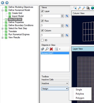
At this step, you can digitize a polyline or polygon, and set the selected cells as inactive (or vice versa, change inactive cells back to active cells)
| · | Select the desired flag from the combo box under "Inactive Cells" (make Active cells Inactive, or make Inactive cells Active) |
| · | Select the Assign button. |
| · | Choose the desired shape for drawing (Single, Polyline, or Polygon) |
| · | Use the left mouse button to start drawing in the grid view, and add highlight the desired cells; for single cell selection, a point will appear on top of the selected cell. |
| · | Once you have finished digitizing, right click with the mouse and select "Define Attributes" (or click on the "Finish" button under the toolbox); the following window will appear. |
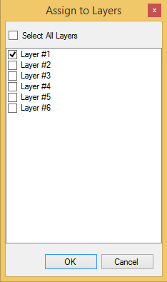
| · | Choose which layers you wish to include in the cell assignments; by default, just the current layer is selected, however you can select other (or all) layers from this window |
| · | Click OK |
| · | The selected cells will be set as Inactive or Active, depending on the option you have selected. Inactive cells will be colored turquoise. |
When you are finished with viewing the grid, click ![]() (Next Step) to proceed to the Define Properties step.
(Next Step) to proceed to the Define Properties step.
|
Once the model Run has been generated, it is not possible to make further edits to the numerical grid (such as coarsening or refining). However, a workaround to this is to create a new numerical grid, then populate this grid with the conceptual objects that are defined when you do cell-based editing. You can create an additional grid for your model by right-clicking on the "Model Domain" folder under the model tree, and selecting "Create Finite Difference Grid". Create the desired grid, and make the necessary edits (you can right click on the grid to access the "Edit Grid" or "Define Child Grid" options explained above. Once the grid is finalized, right click on this new grid in the tree, and select "Convert to Numerical Model..." . This will run a conversion routine that populates the new grid with the conceptual data that were defined while creating inputs for the first grid. You can then proceed through this new workflow to run the model for this adjusted grid. |